The inherent demand profile—characterized by high, instantaneous peak loads and intermittent operation—presents unique challenges to air supply synchronization. Inadequate system sizing or inappropriate control strategies result in undue stress on system assets and disproportionate resource consumption. Furthermore, failure to ensure air quality, specifically addressing dew point consistency and contamination control, directly compromises mold longevity and component dimensional stability.
This technical analysis details a methodology for accurate air system engineering. We move beyond nameplate parameters to establish the true CFM and PSI requirements, evaluate the operational profiles of various compressor platforms, and outline the factors that determine long-term asset longevity and optimized operational efficiency for your manufacturing environment.
Understanding the Relationship Between Injection Molding Machines and Air Compressors
The relationship between the injection molding machine and its air supply is one of fundamental reliance. Compressed air is the engine driving the machine’s ancillary and critical path mechanics, where the supply system’s performance directly determines the integrity of the molding process.
Pneumatic Demands and Actuation
Specific functions within the molding cell impose distinct, rapid demands on the air supply:
- Mold Actuation: Precision cylinders require immediate and sustained pressure for rapid core pulls and accurate ejector pin movements. Any pressure deviation during these phases can compromise the part’s geometric tolerances.
- Resin Transport: Air is essential for transferring raw material (resin pellets) via vacuum or pressure conveying systems, demanding consistent flow volume to prevent material starvation at the hopper.
- Auxiliary Process Support: This includes air knife systems for accelerated demolding and separation, as well as powering other downstream handling mechanisms.
Pressure, Flow Dynamics, and Specification
Injection molding operations typically specify required operating pressures in the range of 80 to 120 PSI (5.5 to 8.3 bar), determined by the force required for the largest pneumatic components. Crucially, the system must be sized for peak demand, not just the average consumption.
A representative 50-ton machine might have an average consumption of 15-20 CFM, yet the momentary activation of core pulls can generate an instantaneous load spike far exceeding this average. This acute, short-duration requirement necessitates an air system capable of dynamic flow response without succumbing to system pressure decline.
Maintaining Process Integrity
The quality of the air delivered—specifically its purity and dryness—is non-negotiable and affects the longevity and reliability of interconnected components:
- Moisture Content: High dew points introduce condensation, leading to accelerated corrosion and premature failure of sensitive pneumatic valves and cylinders.
- Contaminants: Particulate matter or residual oil jeopardizes the internal mechanisms of mold ejector systems and contaminates the transported resin, potentially impacting the material’s structural consistency.
Therefore, the air system’s ability to maintain consistent pressure under peak load and guarantee cleanliness and dryness is the fundamental technical mandate for reliable injection molding operation.
Key Criteria for Selecting the Right Type of Air Compressor
Compressor Types and Their Suitability for Injection Molding
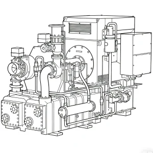
Rotary Screw Systems
Positive-displacement units that serve as the industry standard for base-load and critical operations.
Characteristics
- Designed for sustained output and base-load reliability.
- Provides high pressure stability with minimal pulsation, ensuring consistent molding cycles.
- Integration of VSD technology is critical for precise matching of fluctuating airflow demands.
Reciprocating (Piston) Systems
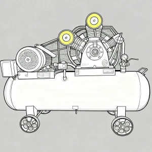
Compressors best specified for low-volume, intermittent auxiliary applications or specialized systems requiring high pressure capability (up to 175 PSI).
Characteristics
- Suitable for high standby periods and intermittent operation.
- Capable of achieving high pressure head.
- Inherent air pulsation requires robust attenuation via adequate system receivers (air tanks).
Centrifugal Systems
Dynamic compression units utilized for large-scale, centralized air systems where high volumetric flow (CFM) is the primary requirement.
Characteristics
- Suitable for large-scale, centralized systems to achieve high volumetric flow.
- Dynamic compression design inherently generates oil-free air output.
- Applicable for facilities with the strictest air purity mandates.
Technical Mandates for System Integrity
Air Quality Specification
The purity and dryness of the compressed air are technical mandates, as contaminants directly threaten the longevity of pneumatic components and compromise finished product quality. All air systems must adhere to ISO 8573-1 Standards:
| ISO Air Quality Class | Solid Particles (μm) | Water Content (Dew Point) | Oil Content (mg/m³) | Technical Application Requirement |
|---|---|---|---|---|
| Class 1 | ≤ 0.1 | -70°C | 0.01 | Critical tolerance components; pharmaceutical/medical-grade plastics. |
| Class 2 | ≤ 1 | -40°C | 0.1 | Food contact packaging, sensitive electronics. |
| Class 3 | ≤ 5 | -20°C | 1 | General-purpose industrial molding and actuation. |
Facility Integration and Service Planning
Platform selection impacts key logistical considerations for plant operation:
- Acoustic Management: Noise output varies significantly; reciprocating units frequently exceed 85 dB, often requiring remote installation. Modern rotary screw designs typically operate in the lower 65–75 dB range.
- Service Protocol: Reciprocating units demand more frequent, though simpler, maintenance checks. Rotary screw platforms offer extended service intervals but require specialized procedures during their scheduled overhauls.
Essential Methodology for System Specification
Accurate sizing is fundamental to system reliability and is achieved by precisely quantifying the flow (CFM) and pressure (PSI) requirements, factoring in the unique operational environment.
CFM Specification Methodology (Flow Determination)
Proper sizing must account for the difference between the sum of individual component flow requirements and the facility’s actual demand profile (peak vs. average).
- List all air-consuming equipment in your injection molding operation.
- Determine the maximum CFM requirement for each piece of equipment.
- Establish the Diversity Factor (typically 60–80% for injection molding) for the entire air system, reflecting that not all equipment operates simultaneously at peak flow.
- Calculate the Adjusted CFM Requirement by summing the flow and applying the Diversity Factor.
- Integrate a Contingency Margin (10–20%) to accommodate unmeasured system leaks and future operational expansion.
Example: A facility with two injection molding machines (20 CFM each), material handling (15 CFM), and auxiliary equipment (10 CFM) would calculate: (20 × 2 + 15 + 10) × 0.7 Diversity Factor × 1.2 Contingency Margin = 54.6 CFM Required Capacity.
Pressure Setpoint and Distribution Integrity
The compressor’s operational pressure must be set based on the highest requirement among connected equipment, not just the molding machine itself.
- Identify the maximum pressure requirement for any component in the system.
- Add a System Distribution Buffer (10–15 PSI) to mitigate pressure losses across the piping network.
- Distribution Loss Mandate: Pressure depletion occurs through the network. Plan for approximately 1–2 PSI pressure drop per 100 feet of correctly sized piping, plus additional measurable drops across dryers, filters, and other purification components. Most systems require the compressor to deliver 100–115 PSI to ensure the point-of-use pressure remains within the 90–100 PSI working range.
Load Profile Management
Analyzing the production schedule dictates the necessary system responsiveness required to maintain pressure stability.
- Unmodulated Load Profile: If air demand remains remarkably consistent with minimal fluctuation, a Fixed-Speed platform may be optimal for providing a consistent, unmodulated supply.
- Dynamic Load Profile: If the operation experiences significant shifts in demand (due to cycling, varied product runs, or start/stop periods), a Variable-Speed platform is essential for dynamic pressure maintenance and precise resource modulation throughout the load changes.
Environmental Derating Factors

System capacity is inherently affected by installation conditions and must be accounted for during specification:
- Ambient Temperature: For every 10°F increase in ambient temperature above 70°F (21°C), the platform’s compressed air capacity is reduced by approximately 2%.
- Altitude: For every 1,000 feet (305 meters) above sea level, the available compressor capacity decreases by approximately 3% due to reduced air density.
Combining Selection and Sizing for Optimal Performance
Matching Compressor Type to Application Requirements
The following scenarios outline appropriate compressor platform specifications based on the facility’s scale and operational profile:
| Operation Type | Platform Specification | Key Operational Benefits |
|---|---|---|
| Micro-Scale Molding (1–2 units) | Rotary Screw (15–30 HP) with receiver | High system fit; sufficient storage capacity for intermittent peak demand stability. |
| Mid-Volume Production (3–5 units) | Rotary Screw (30–50 HP) with VSD | Adaptable dynamic pressure management; consistent resource delivery under varying load. |
| High-Volume Production (6+ units) | Multiple Rotary Screw Units with Master Controller | Operational continuity via redundancy; optimized load sharing across assets; servicing configuration adaptability. |
| Critical Purity Applications (Medical/Electronics) | Oil-Free Rotary Screw with Multi-Stage Filtration | Contaminant exclusion; preservation of product dimensional stability; regulatory adherence. |
System Design Considerations
Beyond selecting the right compressor, consider these system design factors for optimal performance in injection molding applications:
Air System Architecture & Integrity
- Air Purification: Refrigerated or desiccant dryers and multi-stage filtration are mandatory to meet required Dew point and purity mandates (ISO 8573-1), preserving critical pneumatic component life.
- Pressure Management: Correctly sized and looped piping is essential for preserving system pressure across all drops. Air receivers stabilize fluctuations and provide an immediate reserve supply for transient demand spikes.
- Distribution Integrity: A formal leak detection and repair program is required to preserve overall system capacity and ensure stable pressure at the point of use.
Performance and Life-Cycle Management
- Predictive Diagnostics: Remote monitoring and predictive alerts maintain operational continuity. Automatic sequencing logic achieves synchronous load sharing across multiple units to stabilize system pressure.
- Asset Life-Cycle Focus: The largest proportional allocation of resources over an asset’s life is dedicated to continuous system operation (power draw). The initial platform procurement is a minor proportional allocation. Prioritizing platforms with superior dynamic resource modulation capability is therefore key to stable long-term operation.
Total Cost of Ownership Analysis
When making your final decision, conduct a thorough total cost of ownership (TCO) analysis that includes:
Remember that energy costs typically represent 70% of the total lifetime cost of an air compressor. Investing in energy-efficient technology often provides the best long-term return, especially for injection molding operations that run continuously.
Conclusion
Implementing a precision-matched air compressor platform is a fundamental engineering mandate that secures process integrity and uninterrupted operational continuity. By applying the rigorous methodology outlined in this analysis, facilities can design a system architecture that functions in complete synchronization with the demands of the molding process.
Key Technical Directives
To ensure the long-term viability and stability of your compressed air system, adherence to these technical directives is essential:
- Define Specification: Accurately quantify the CFM, pressure setpoint, and ISO air quality mandates before platform evaluation.
- Balance Allocation: Prioritize platforms with superior dynamic resource modulation capability over initial procurement to stabilize long-term operational resource allocation.
- Match Load Profile: Align compressor technology (Fixed-Speed vs. VSD) with the facility’s dynamic or unmodulated load profile to ensure stable pressure delivery.
- Integrate Margins: Incorporate a systematic Contingency Margin (10–20%) to account for systemic growth and unmeasured distribution losses.
- Architectural Mandate: Implement robust air treatment, pressure management (receivers and looped piping), and a formal Distribution Integrity program.
- Ensure Continuity: Utilize modern control systems for Predictive Diagnostics and automatic sequencing to maintain synchronous load sharing across multiple units.
The correct system specification yields more than just an operational machine; it delivers a foundation of consistent pressure and validated air purity, protecting your geometric tolerances and securing the long-term performance of your injection molding assets.
Need Expert Guidance for Your Injection Molding Air Compressor?
Our team of compressed air specialists can help you determine the exact requirements for your specific injection molding application. Contact us today for a personalized consultation and air system assessment.